
Wormhole Culverts Part 5
“What’s the best shape for a wormhole culvert?”
- Wormhole Culverts Part 1: Introducing the wormhole concept
- Wormhole Culverts Part 2: Using wormhole culverts for internal boundary conditions
- Wormhole Culverts Part 3: Comparing wormhole culverts to 1D/2D bridges and culverts
- Wormhole Culverts Part 4: Sensitivity analyses for wormhole culverts
- Wormhole Culverts Part 5: What’s the best shape for a wormhole culvert?
May 2018 update
[PLEASE NOTE: Wormhole culverts have become obsolete with the release of HEC-RAS Version 5.0.4. See our new article on what’s new in 5.0.4 for instructions and videos on using the new culvert options.]
Some recent questions were posted on the HEC-RAS blog regarding the optimal shape of the SA/2D Area Connection alignment for a wormhole culvert – in particular, whether a “Z” shape or “S” shape would be preferable. My apologies in advance for the drawn-out response, but I’ve had this question come up a number of times in class and thought I’d post some of my whiteboard sketches along with some random thoughts on the topic:
“Z” or “S”?
If you draw a “Z” shape, the order in which the vertices are entered will determine the direction of flow (always oriented from left to right looking downstream in HEC-RAS). The following image shows four different ways to draw a “Z”-shaped connection along with the associated orientation of flow that will be assumed in HEC-RAS. In the case of a wormhole culvert, flow could enter the “wormhole” at any of the green arrows (or at any point along each of the adjacent faces) and exit along any of the faces indicated by the red arrows. Wormhole culvert inlets and outlets typically wouldn’t be located along the diagonal segment of the “Z”, but directional arrows are shown along those segments to illustrate how the orientation of flow is preserved along the entire shape:
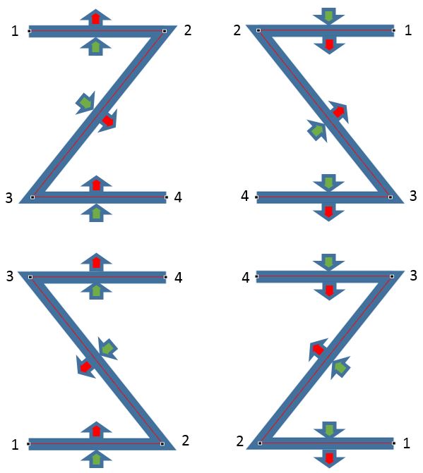
(click on any of the images in this article to enlarge)
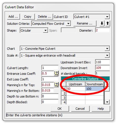
The relative locations of the culvert inlet and outlet are assigned by the chainage/stationing measured from Point #1 along each of the shapes. The screenshot of the culvert data editor below shows where the station values are entered. The upstream centerline station would be reflected in the location of the green inflow arrows in our sketch above, and the downstream centerline station would indicate the location of the red outflow arrows (length along the delineated connection measured from Point #1).
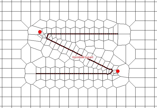
In general, a smooth “S” shape may be preferable to the “Z” shape in order to avoid mesh errors (shown in the geometric data editor as red dots) that can otherwise appear around the corners of the “Z” when you enforce the connection as a breakline. The “Z” shape is also notorious for causing discrepancies between the length of the terrain centerline and the length of the weir embankment (which tend to occur when the connection line can’t snap to a cell face.) Here is an example:
Because of these issues, I actually prefer to use an intermediate shape that looks like a block “S” or a number “2”. This helps to minimize the number of vertices while still avoiding mesh errors. The following image shows mirrored examples of the “Z” and the block “Z” shapes:
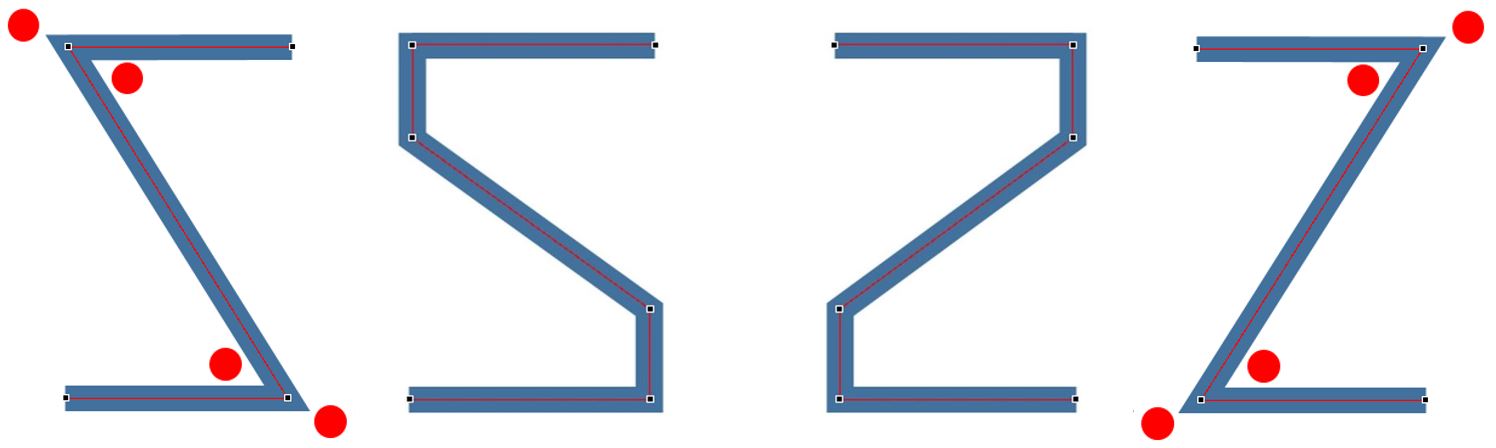
The pesky red dots tend to disappear with the two additional vertices. Limiting the shape to a simple block outline (as opposed to delineating a smooth “S” with an excessive number of vertices) makes it easier to adjust individual vertices later and replicate those changes in any associated GIS files.
[I always like to define breaklines, connection lines, profile lines, and other geospatial data in CAD or GIS shapefiles outside of HEC-RAS so that the shapes will be recoverable and reproducible in other projects; another advantage of having everything defined as a shapefile is that your structures and other features can then be viewable as Map Layers in RAS Mapper as well as in the Geometric Data Editor.]
Here are some options for connection alignments shown relative to the roadway deck and culvert alignments. The shapes below would typically be used to transfer flow from the inlet (green arrow) to the outlet (red arrow).
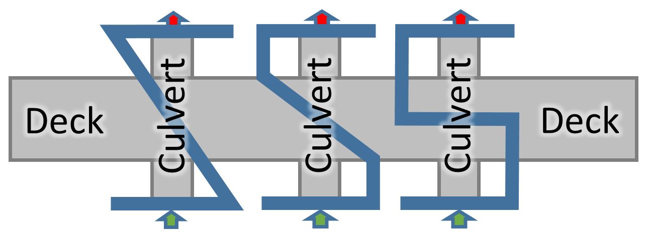
I tend to prefer the alignment on the right so that when I enforce it as a breakline, it orients the computational mesh faces along the roadway. I usually have a breakline running along my roadway anyway; additional mesh errors can be introduced at the crossing when the wormhole culvert alignment is enforced as a breakline. By using the orthogonal shape, sometimes I can just use the wormhole culvert alignment as my breakline, replacing the breakline along the roadway centreline. In order to do this, you can extend the wormhole culvert alignment as shown below:
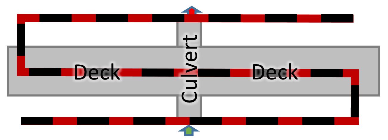 This is my preferred alignment for roadway culverts and bridges. When I enforce it as a breakline, computational mesh cell faces are oriented along flow paths at the toe of the roadway fill as well as along the crest. I avoid issues with overlapping breaklines by replacing them entirely in the roadway area. So long as you don’t exceed 500 points, you can snake it back and forth to represent as many breaklines as you wish. As we saw in a previous article (Part 2), the length of the connection alignment is entirely ignored in the hydraulic computations.
More Shapes
The shapes shown above apply to roadway culverts and bridges; if, on the other hand, you are using a wormhole culvert to move flow to another area in your model, the shape you use will depend entirely on where you want the outflow to end up relative to the inflow. In my previous models I have had to move flow around in all directions in order to apply internal inflow boundary conditions. The connection alignments I have drawn have not just been in the shape of an “S” or a “Z”, but have also included straight lines, spirals, figure eights, and other shapes. I’ll illustrate a few examples below, with the alignment lines drawn from left to right looking downstream. The arrows indicate the direction of flow; inflow enters the culvert in the green cell at the centre of each grid and exits the culvert through the outlet located in the adjacent red cell:
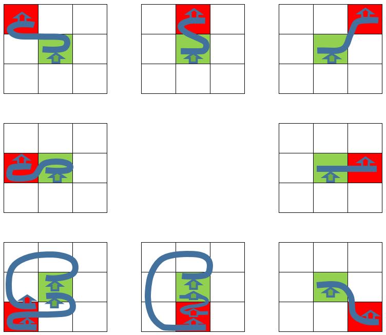
As you can see, if you are merely shifting flow to the east (right), you can delineate the connection simply as a straight line; whereas, if you are moving flow to the south or to the southwest (to the lower left in the previous figure) you have a couple of more involved options to choose from. The matrix above shows simplified cases where flow is always northwards (both at the inlet and at the outlet); the inflow or outflow could obviously be oriented in any direction at all, in which case these shapes could be rotated, extended, or cut short. Again, although these shapes are shown schematically as curves, I would make the actual connection alignment with as few vertices as possible while still avoiding mesh errors.
Sometimes the length of the connection line is only a few metres (when I’m accounting for an actual culvert under a narrow roadway, for instance). In other cases the lines are a kilometre or more in length (like when I’m moving flow from an external 2D Flow Area boundary to an internal inflow location.) Keep in mind that the weir/embankment stationing will be limited to 500 points; so in general if you are trying to move flow over a large distance, you’ll want to go with the shortest possible path between the inlet and outlet that still manages to avoid mesh errors. Also keep in mind that you may need to make slight adjustments to your weir/embankment elevations – even if you have copied them straight from the terrain profile – in order to raise them above the level of the terrain in the cells adjacent to the connection line. This usually requires an adjustment of only a few millimeters and is hopefully a process that will be automated in future versions of HEC-RAS. In the meantime, the longer you make your wormhole culvert alignment, the more points you could potentially have to adjust manually – which provides an argument for avoiding any unnecessary length in your connection line.
As we saw in previous examples (Part 2), however, neither the length nor the alignment of the connection line affects the hydraulic results, provided the flow orientation is maintained and wormhole culvert parameters have been coded in properly. This includes ensuring that the weir embankment elevations are flush with the terrain and that you have selected “use normal 2D equation domain” in the connection data editor window.
Well that brings us to the end of this rather lengthy series of articles on wormhole culverts, which have now become obsolete with HEC-RAS Version 5.0.4.
Q.
“What’s the best shape for a wormhole culvert?”
A.
“Whatever you like, so long as you point the flow in the right direction!”
Read more:
- Wormhole Culverts Part 1: Introducing the wormhole concept
- Wormhole Culverts Part 2: Using wormhole culverts for internal boundary conditions
- Wormhole Culverts Part 3: Comparing wormhole culverts to 1D/2D bridges and culverts
- Wormhole Culverts Part 4: Sensitivity analyses for wormhole culverts
- Wormhole Culverts Part 5: What’s the best shape for a wormhole culvert?
Contact and feedback:
- Please e-mail me any comments or questions about wormhole culverts or other topics
- Contribute to the discussion about wormhole culverts on the RAS Solution blog
- Subscribe to receive updates when new content is published
- Join the newly created LinkedIn groups for dam break modelling and sediment transport modeling
Krey Price
Surface Water Solutions