
Flooding Hobbiton Part 2: Closing the Wormhole
- Flooding Hobbiton Part 1: Saved views and static imagery
- Flooding Hobbiton Part 2: Closing the wormhole
- Flooding Hobbiton Part 3: What’s new in HEC-RAS 5.0.4
This is the last of our articles that will include wormhole culverts, since they have become obsolete with the advent of HEC-RAS Version 5.0.4.
In order to set up a comparison to the new culvert features available in 5.0.4, we’ll first compare the most common culvert options available in 5.0.3 side by side.
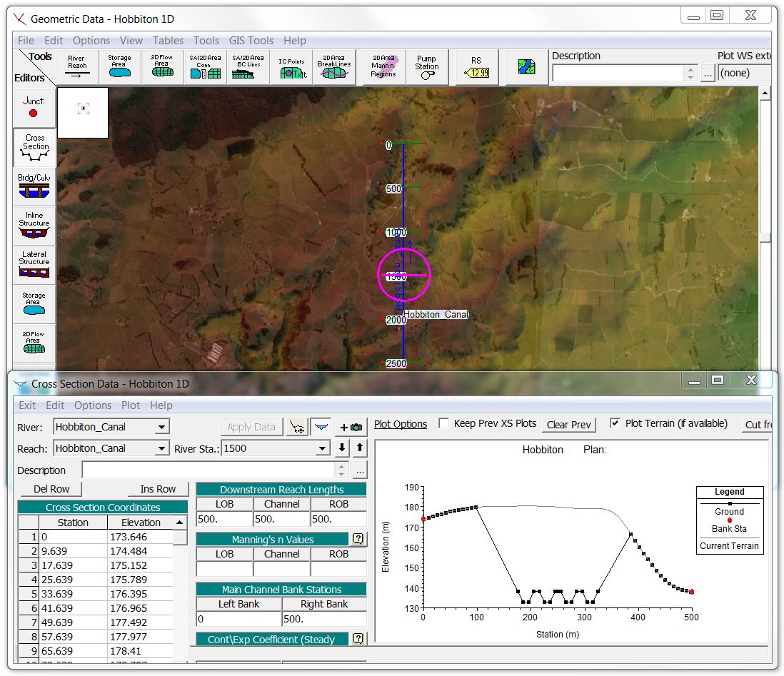
For this first exercise, we’ll start with the Hobbiton terrain (see Saved Views & Static Imagery article for the free data sources if you want to follow along) and dig a canal straight through the middle of the Shire to connect the Hobbits with their trading partners.
[By the way, I’m using the same channel and bridge configuration that we cut through Sydney to flood the Opera House in our wormhole culvert tutorials.]
In order to incorporate the canal into the terrain, I created a 1D reach with a uniform cross section that included four parallel trapezoidal channels for comparing various culvert methods:
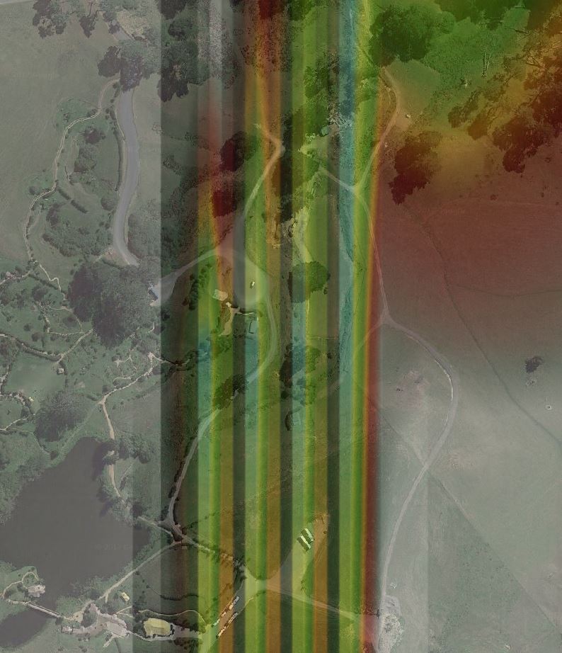
Next I exported the geometry to a geotif and made a new merged terrain file incorporating the Hobbiton Canal at a 1-metre resolution (see Terrain Modification article for more details on the individual steps).
Here’s the merged terrain with the canals right next to the Hobbit-holes:
Now just for fun, I thought I’d see if an Orc-dam across the Brandywine River would flood out Bag End with the new canals in place:
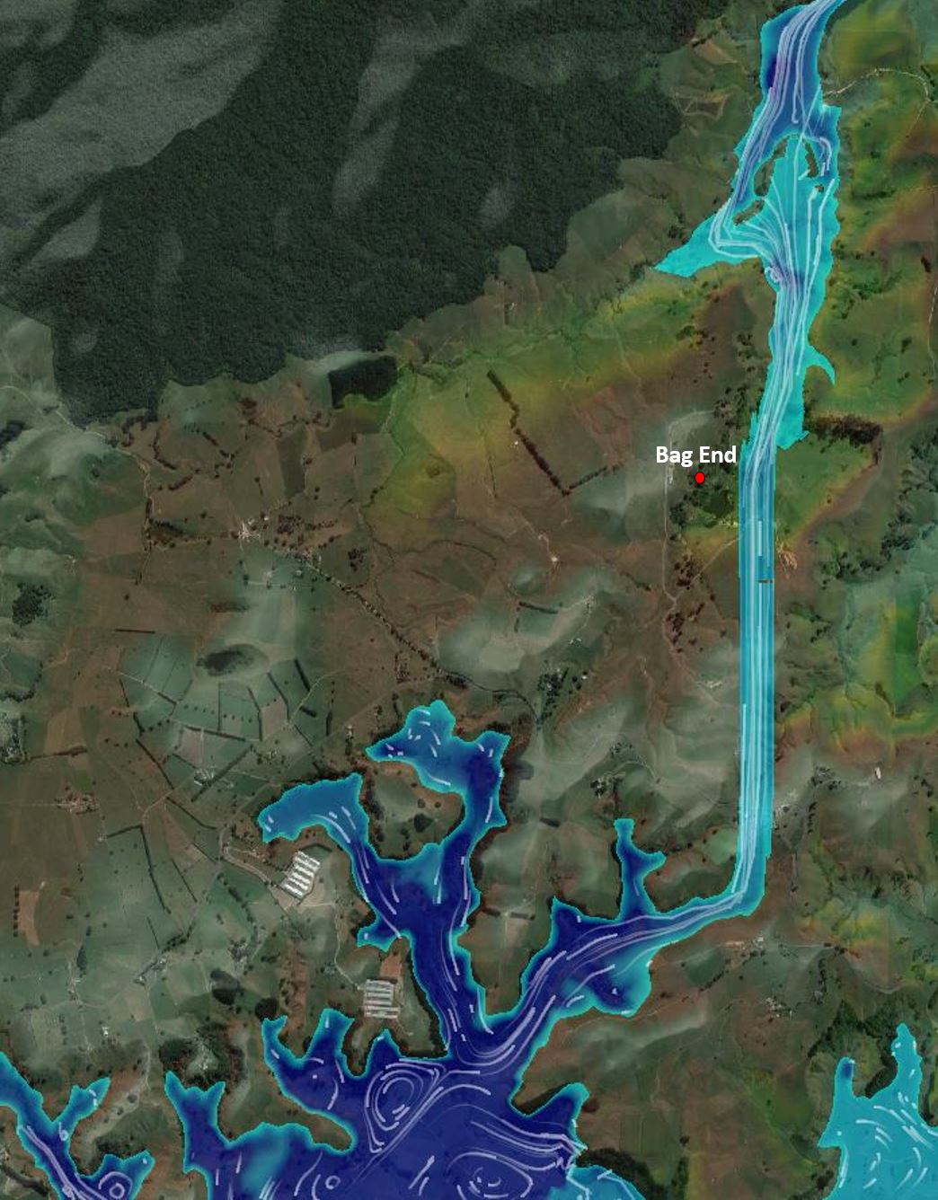
Looks like we’ll need a bigger flood! But first let’s get to the culverts. For this exercise, I’ll start by comparing the following culvert methods available in Version 5.0.3:
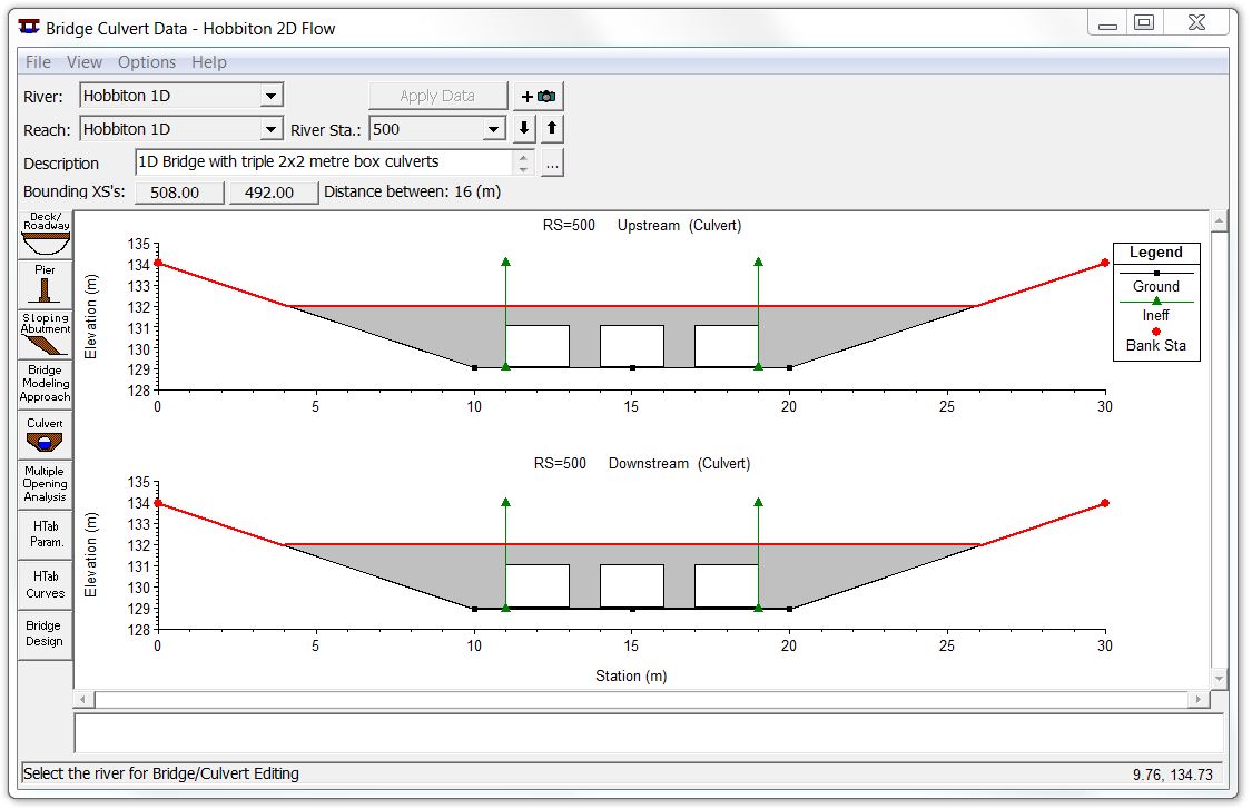
- Standard 1D culvert. For 1D culverts, the road deck is not included in the cross section data but rather is reflected in the weir data of the bridge/culvert deck editor.
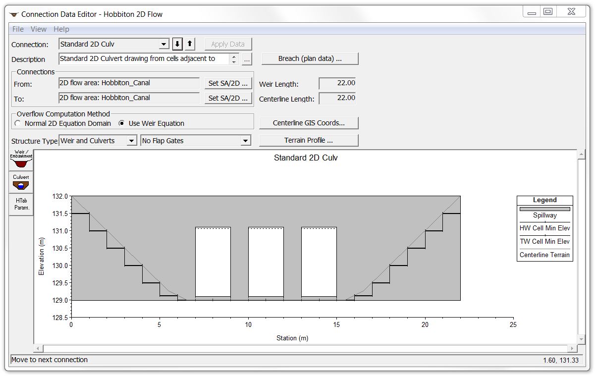
- Standard 2D culvert. For standard 2D culverts, the road deck is not included in the terrain data but rather is reflected in the weir data with an SA/2D Flow Area Connection that follows the roadway centreline.
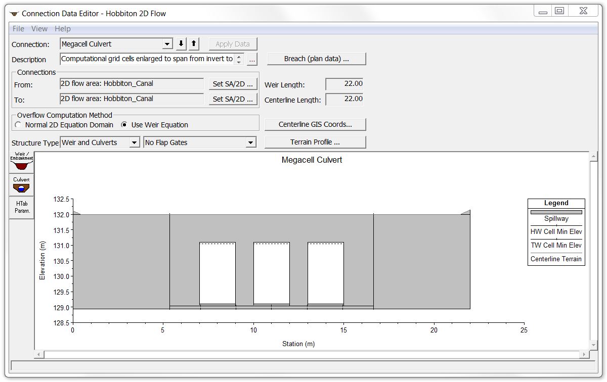
- “Mega-cell” 2D culvert. Also known as a C.O.U.S. (Cell Of Unusual Size) culvert, a mega-cell culvert has the road deck included in the terrain and is created by enlarging the cell size until the two cells immediately adjacent to the upstream and downstream side of the SA/2D Flow Area Connection line both have a face at the top of the deck and at the culvert invert/channel thalweg.
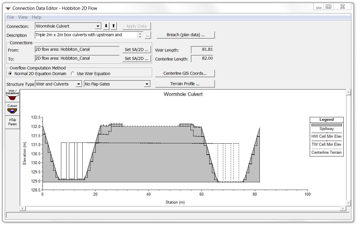
- Wormhole 2D culvert. A wormhole culvert has the road deck included in the terrain data and moves the inlet and outlet locations along the alignment path using differing upstream and downstream stationing.
[A fifth option that we’ve left off here but will explore in a dedicated article of its own is the representation of bridge piers in the 2D terrain without the deck – which only works if you won’t be encountering pressure flow or overtopping flow.]
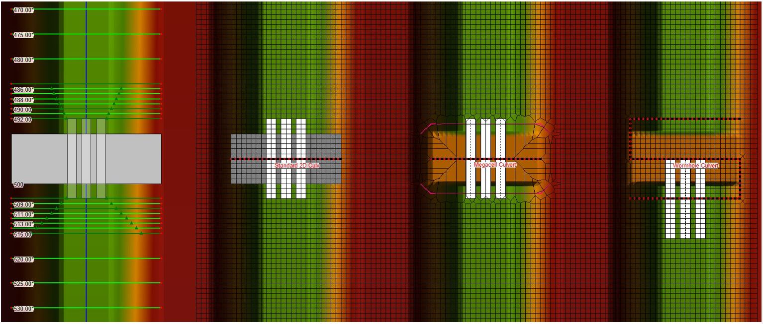
Before entering the culvert details, I used terrain modification to incorporate the bridge decks for #3 and #4. Next I entered a set of three 2-metre by 2-metre concrete box culverts along each channel, with a bridge deck one metre above the culvert soffit. I used the same configuration for each set of culverts and put a 1-metre by 1-metre computational grid around the entire canal. Here is a schematic plan of the four culvert options:
Below are some screen shots from the bridge/culvert and connection editors. Here is the 1D culvert:
Here is the standard 2D culvert:
Here is the mega-cell culvert:
And finally the wormhole culvert:
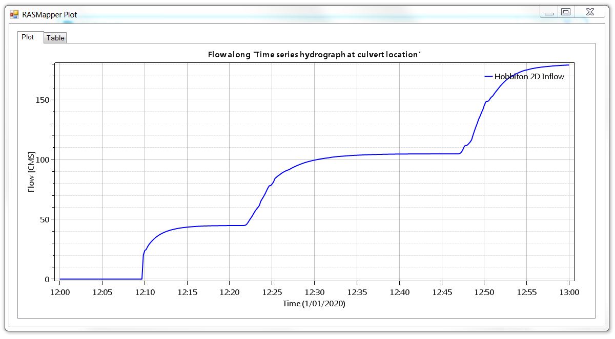
I applied identical inflow hydrographs to each canal, holding the flow rate constant at three different levels long enough to reach steady flow conditions for open channel flow, pressure flow, and overtopping flow conditions. Here’s an inflow hydrograph along with the total flow hydrograph measured across a profile line at the culvert location:
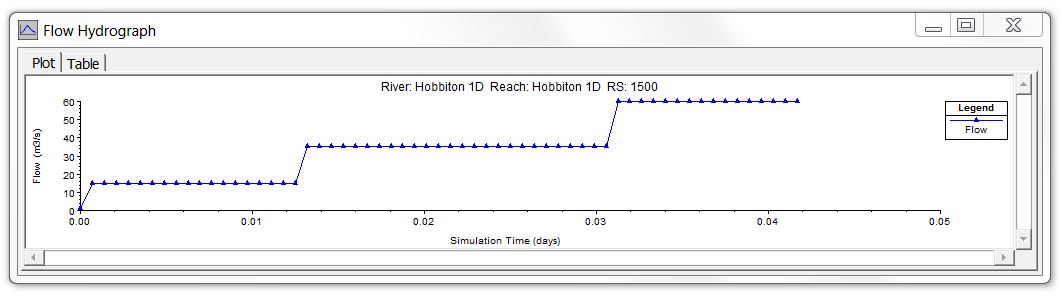
And here is the profile animation from the 1D results showing the three levels:
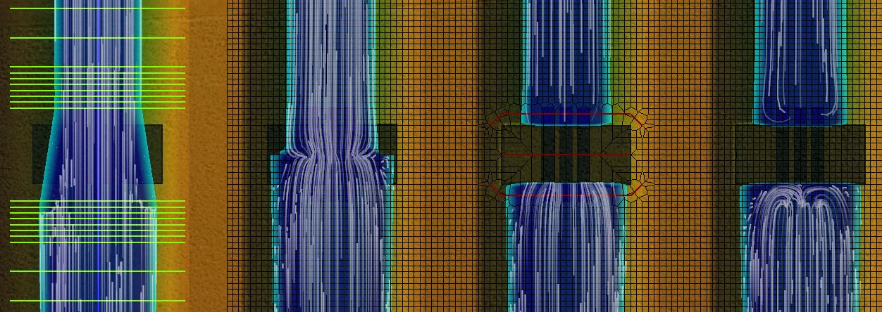
Here’s a plan view of the results in RAS Mapper with the underlying cell and cross section configuration shown (click to enlarge):
Here are animations showing the flow paths for the open channel, pressure flow, and overtopping flow scenarios:
A few items worth noting:
- In the 1D model in #1 at the left, you can see the ineffective flow areas that were manually input into the cross sections, but it does not show the internal culvert hydraulics.
- In the standard 2D culverts in #2, you can see the “glass wall” weir that displays without any width, transferring flow only from cells immediately adjacent to the connection line.
- In the mega-cell 2D culvert in #3, you can see, the interpolation issues associated with the large cell size, resulting in an apparent dry spot on the deck, even when it’s completely overtopped.
- In the wormhole 2D culvert in #4 at the right, you can see the direction of flow in and out of the individual culvert barrels.
These animations illustrate why I am such a big fan of wormhole culverts: In Version 5.0.3, it was the only way to get flow actually entering individual culvert barrels from the 2D cell covering the barrel inlet and exiting into the cell covering the outlet. The pressure flow scenario shows a good example of this. Both the inlet and outlet are submerged; since the culverts are protruding on both sides, you see reverse flow against both the upstream and downstream bridge deck faces as you might expect in reality.
Here are the water surface elevation profile results for 15 m3/s (open channel flow), 35 m3/s (pressure flow), and 60 m3/s (overtopping flow), comparing the four culvert methods to each other:
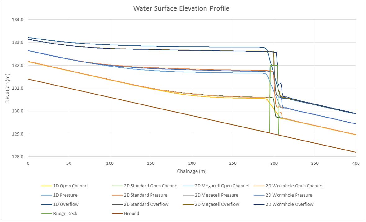
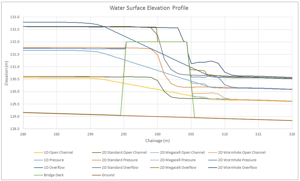
The 1D results differ slightly from the rest, but we should note that these results are from RAS Mapper, which does not display the internal culvert hydraulics. If we wanted to see what’s going on inside the culvert, we could have a look at the 1D internal culvert results in the profiles and detailed output tables.
Looking at the backwater profiles for the three 2D methods in the meantime, they are essentially identical. In the area immediately downstream of the structure there are some differences in the way flow is handled between the methods, but the water surface profiles quickly converge to the same level. Your choice as to which method to apply may depend on whether the bridge deck is built into your terrain and whether the deck is long enough to require the assessment of individual cells on the surface of the deck.
[If you don’t need to account for pressure flows or overtopping flows, you may wish to put the piers or culvert walls into the 2D terrain, which is a separate method we’ll cover on its own in a future post.]
In the next article, we’ll take the comparison between culvert methods in Version 5.0.3 and convert the model to Version 5.0.4 to see how it compares.
If there are any questions, or comments, please contact us.
Krey Price
Surface Water Solutions
- Flooding Hobbiton Part 1: Saved views and static imagery
- Flooding Hobbiton Part 2: Closing the wormhole
- Flooding Hobbiton Part 3: What’s new in HEC-RAS 5.0.4